PRINTER
While I worked on the Super Board (/superboard.html), I asked Marcel about the COMX printer interface card. He said he had one and would send it to me when he sent me his second floppy card.
Once again, I wanted to trace it out and draw up a schematic of it in hopes of being able to build one.
Not long after it was shipped, I received the printer card. Marcel wasn't sure if it worked. I told him I would try and get it working if it didn't. The printer card was in great shape, no missing or broken components.
INITIAL TESTING
I installed it in the COMX expansion slot and did a few "PEEK"s into the card's ROM located at C000h-CFFFh. Using the ROM image available with the Emma 02 emulator (http://www.emma02.hobby-site.com/index.html), I was able to confirm that the ROM and address decoder for it was working.
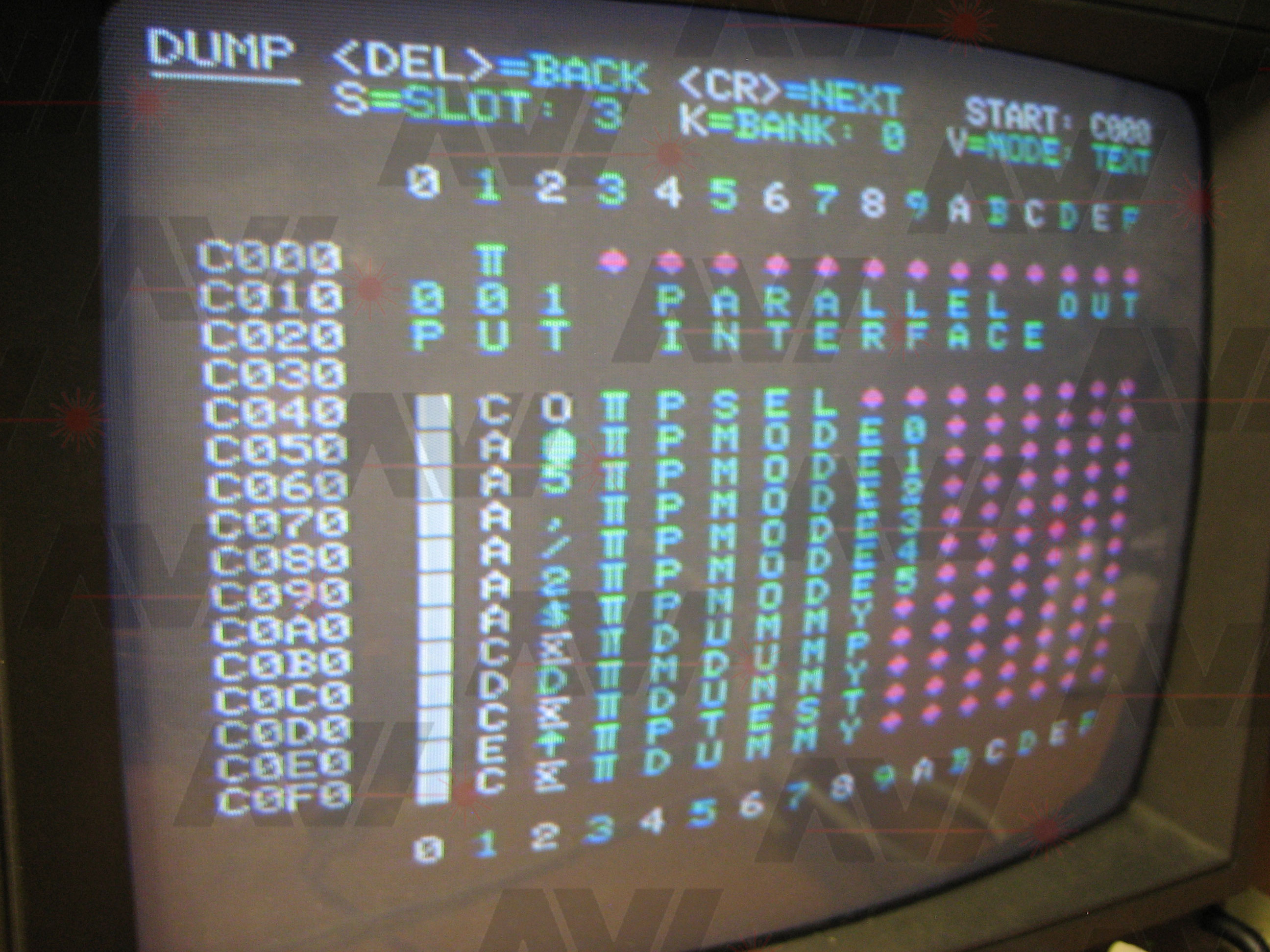
I then installed the card into the Super Board. Using the "F&M Monitor" (http://www.emma02.hobby-site.com/comx_fandm.htm), I was able to see that the printer card was in serial mode.
Marcel told me that the board detects whether a parallel cable was connected. If yes, the board goes into parallel mode. If not, it stays in serial mode. This detection is done by dividing the grounds going to the connector in two. When a cable is installed, these halves get connected. This is detected by the card and switches which half of the ROM to use.
I then began looking for any sort of information on how to actually print something. I couldn't find any information on the net. I asked Marcel if he had any information on the printer card. He sent me what he had which was a PDF of the "COMX PRINTER INTERFACE MANUAL". The tricky part was it was written in Dutch. Other than command formats and a few other small bits, I couldn't read it.
TESTING PARALLEL
It did not work at first but I got it working. Here is what I did:
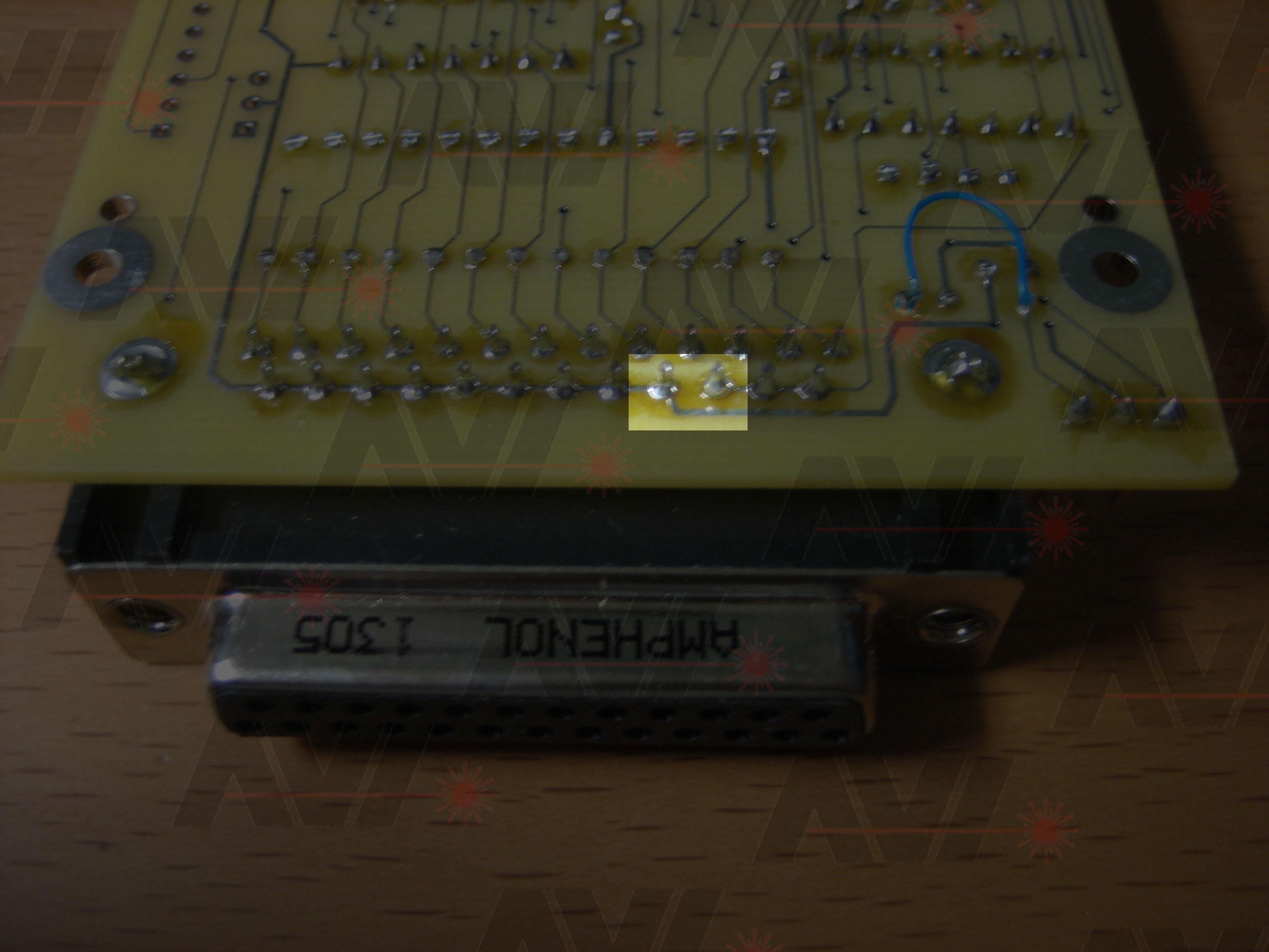
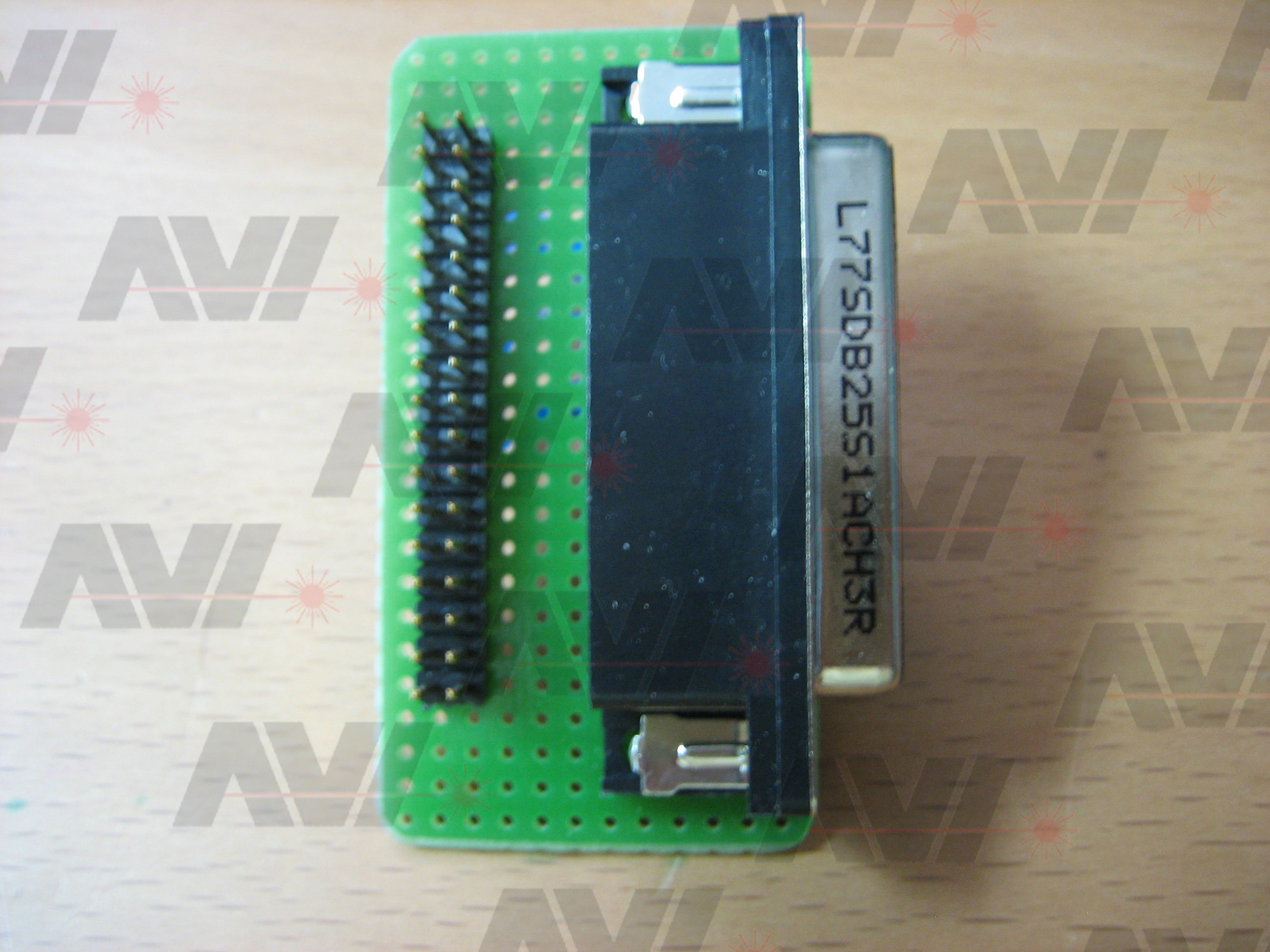
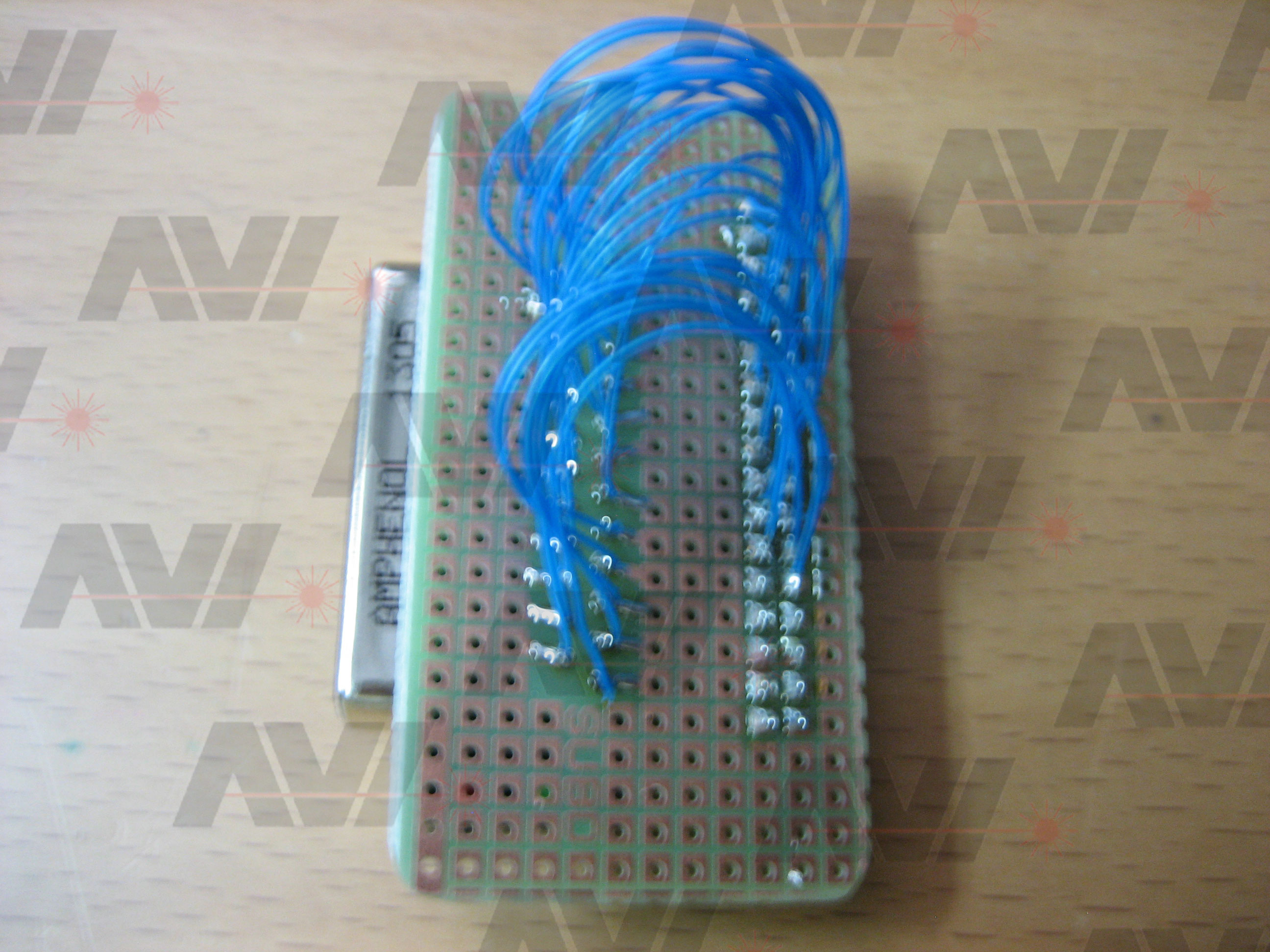
First I built a little adaptor board since the printer card has an IDC 34 pin connector and the printer cable I had has a DB-25 connector:
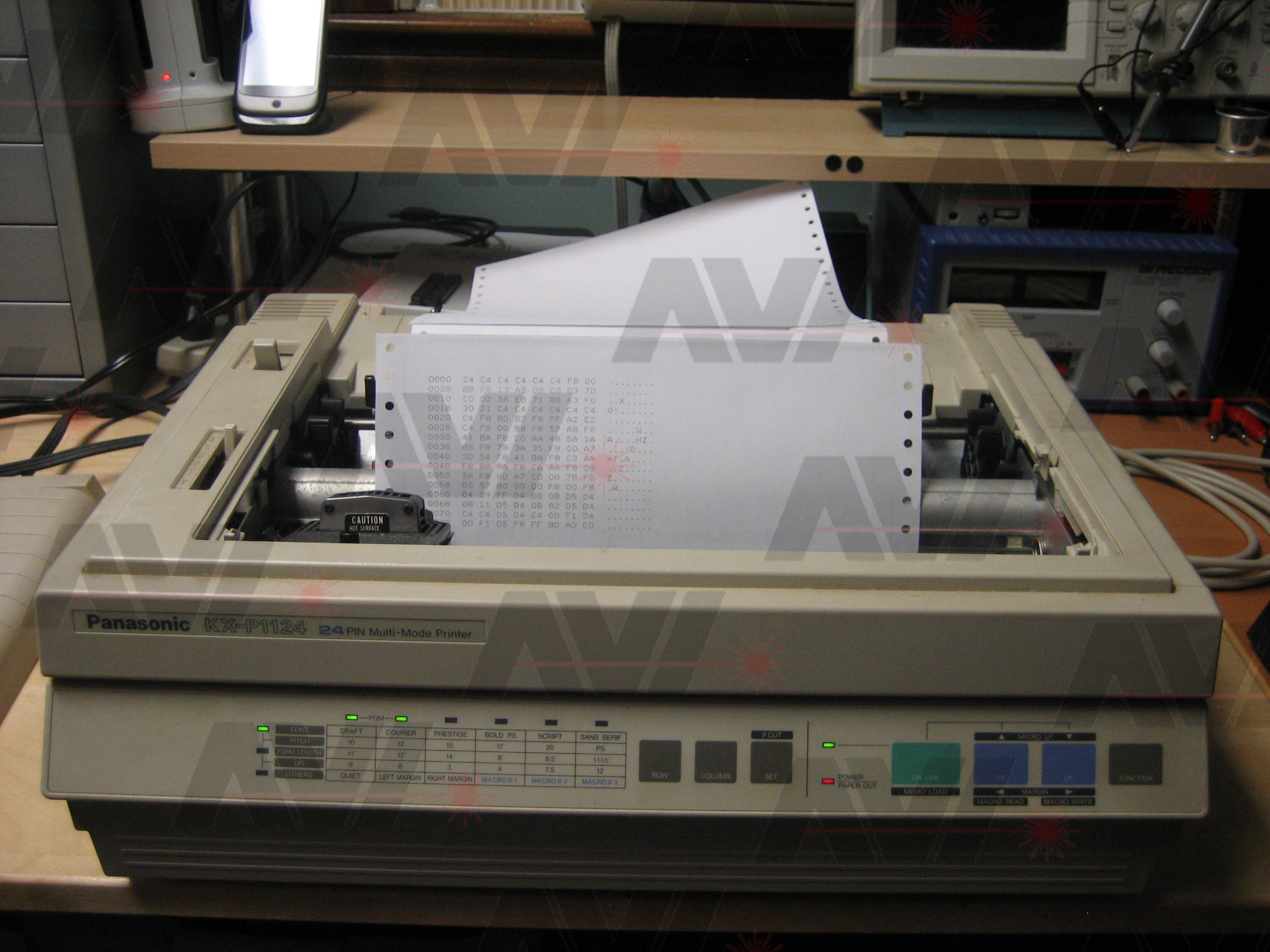
I inserted a standard PC printer cable and hooked the card to my printer. I was using a Panasonic KX-P1124 parallel printer.
No matter what I did it would always get an acknowledge error, even with no cable attached to the board. I was able to force the 'BUSY' and 'PAPER EMPTY' messages. The biggest problem was that after about 3 minutes of being powered on, the COMX (with printer card installed) would act up. Text on the screen would become hard to read and jump from color to color. Commands would not always work.
I probed around the printer card with my scope and looked for bad or missing signals. I found problems with the 74LS04 chip.
I did a test with one of the inverter gates located on pins 12 and 13 of the 74LS04. I found that both were at 2.85 volts. One should have been near 5 volts and the other at or near 0 volts. The gate had an internal resistance of 78 ohms. There should have been a really high resistance. I watched the 5 volt power line from the COMX with my scope and it would stay right around 4.89 volts which is normal. I waited for the problem with the screen described above to occur and noted that the 5 volt line was now hovering at 3.9 volts. Something on the board was internally shorting out after a few minutes of running. I suspected the 74LS04 due to the abnormal voltages on pins 12 and 13.
The 74LS04 chip is the interface for signals coming from the printer. I went ahead and replaced this chip with a new one and the board started working. All voltages were where they should be.
I had to play with the jumpers on the board, but eventually got it to print using the parallel interface.
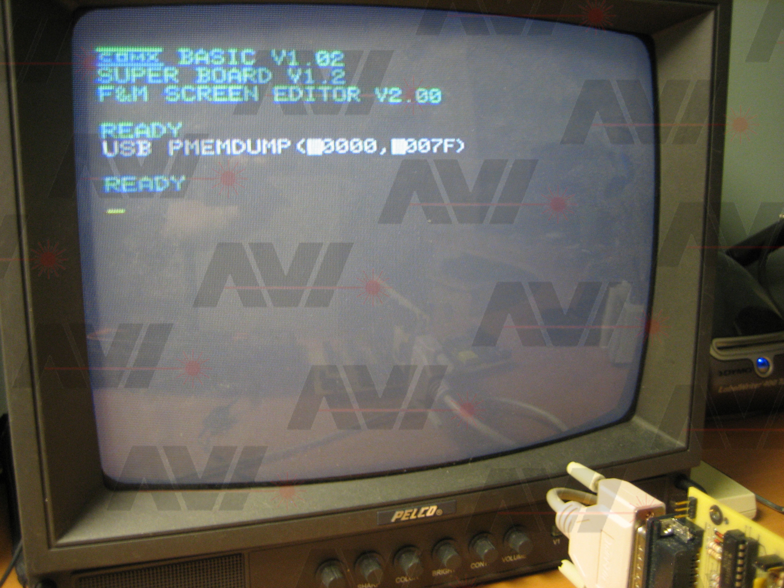
Here is a picture of the command I entered:
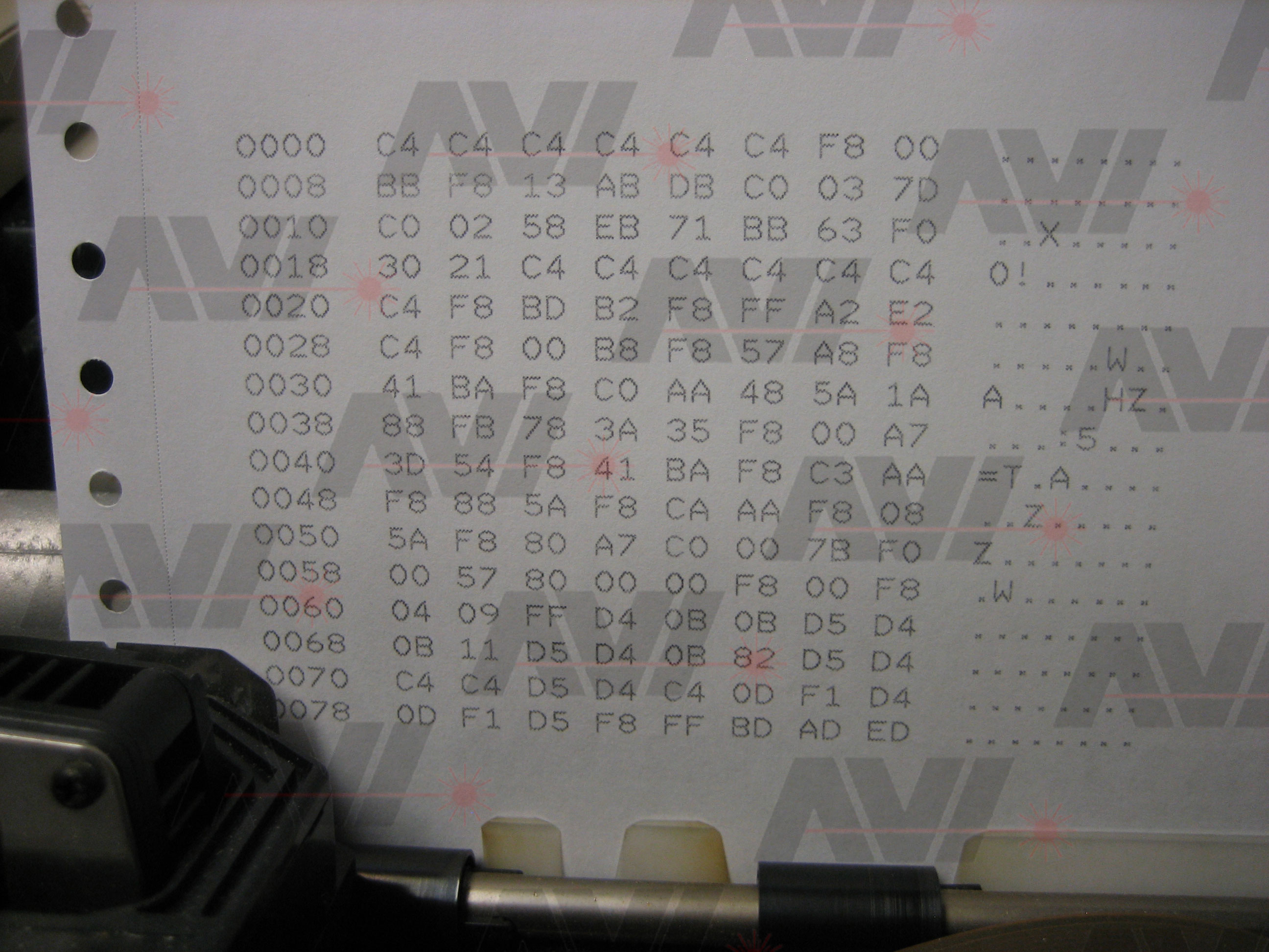
Here is a picture of a printout:
TESTING SERIAL
Now that the parallel portion of the board was working I started testing the serial section of the board.
After messing with the jumpers for a while I was able to see key-presses going out the TX line on my scope. Here is what I saw:
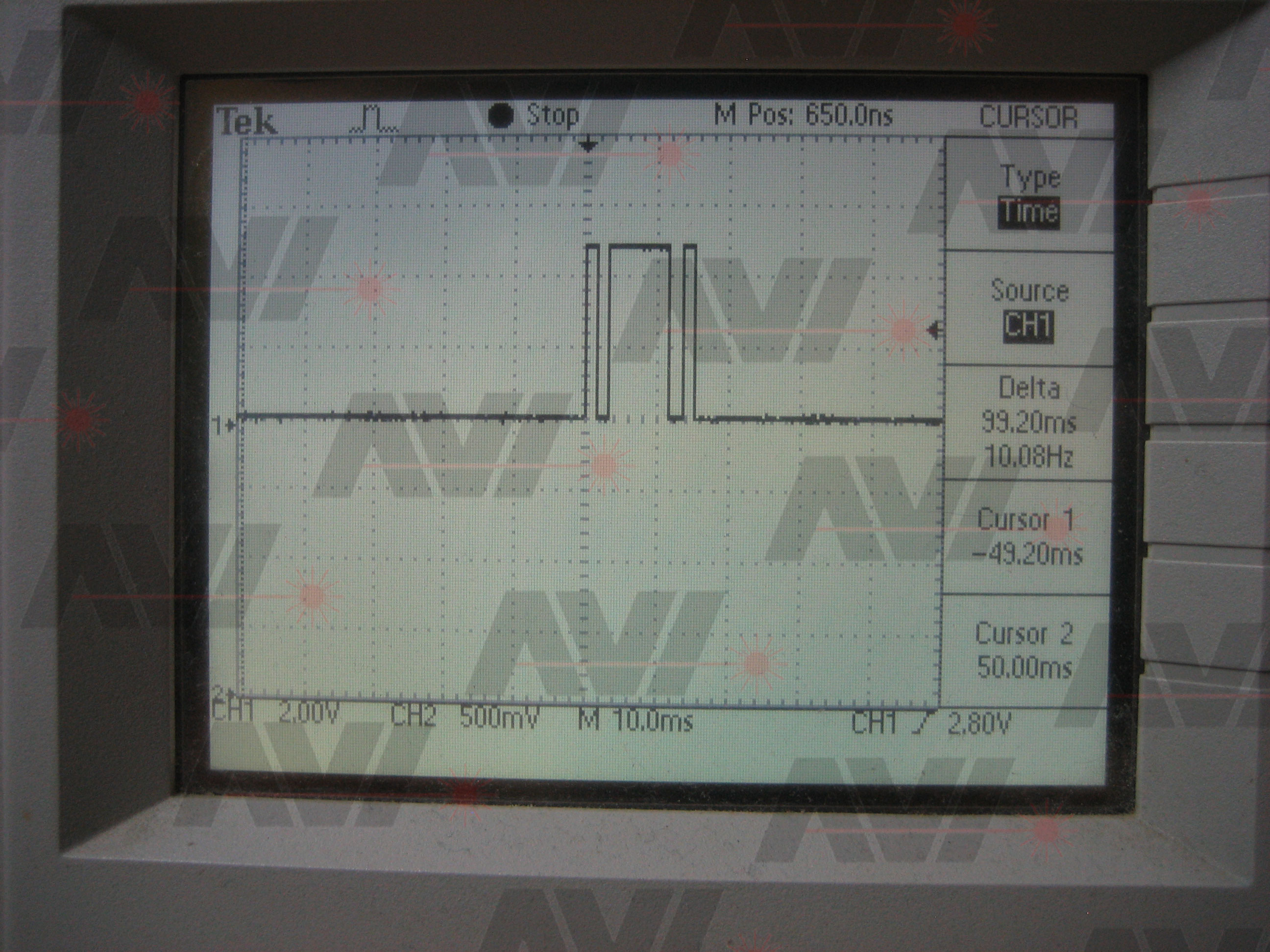
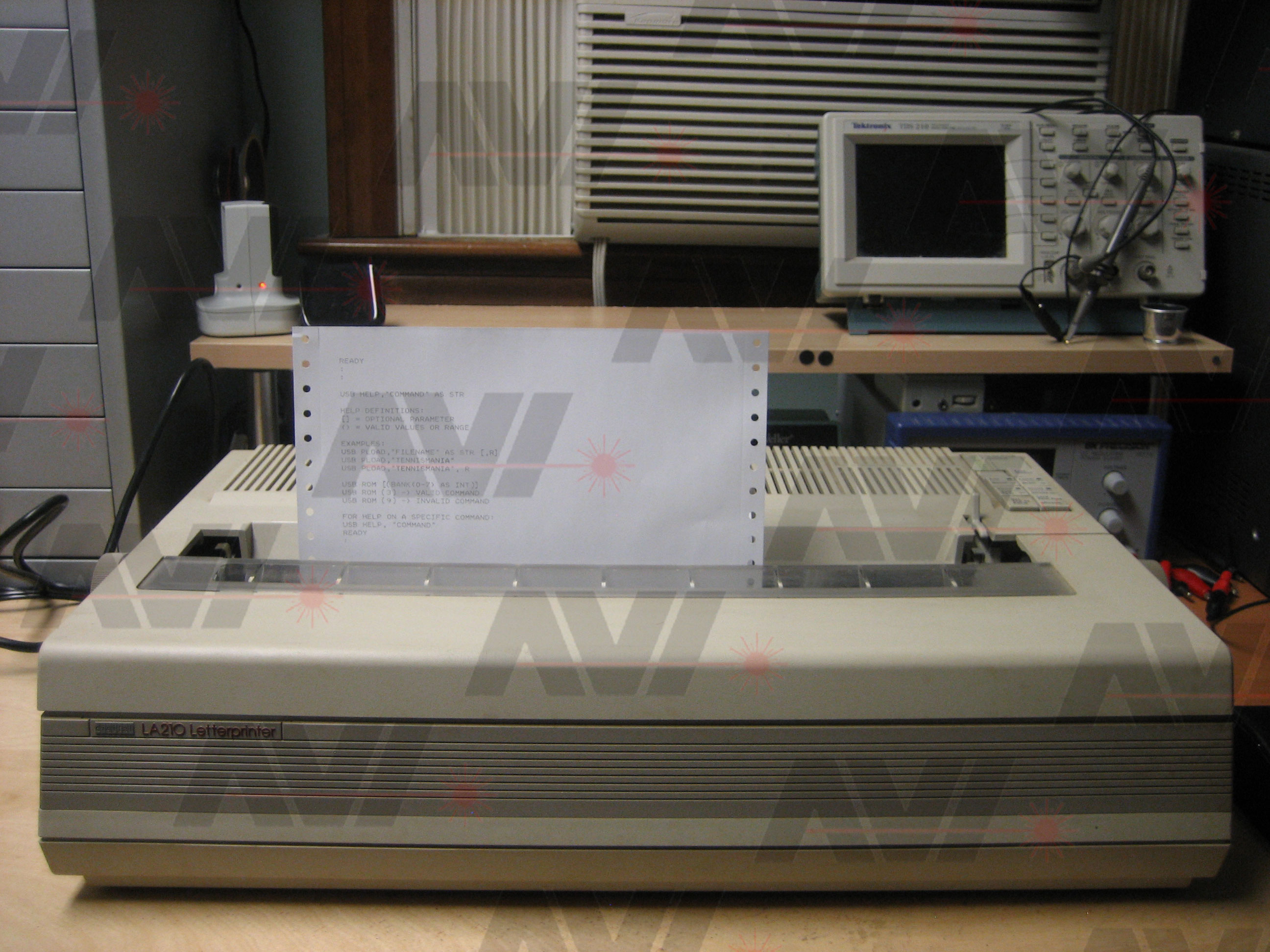
Based on the timing, the baud rate appeared to be 300 baud. I tried using my PC to test the serial output before I trying to interface with my serial printer. Unfortunately, all the software I have, and my Digital LA210 serial printer, only go down to 600 baud.
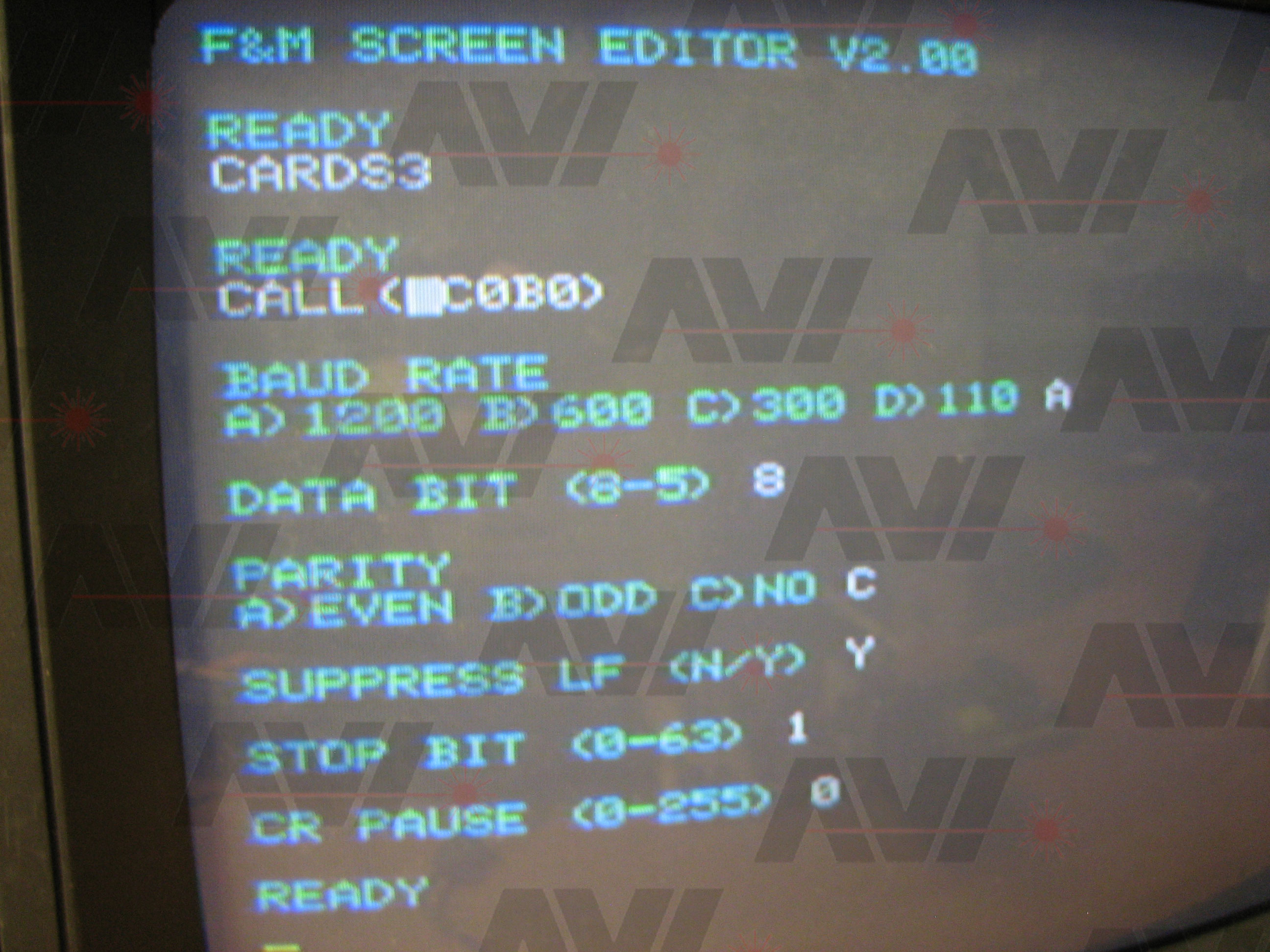
Using the Dutch manual for reference, I tried calling every address in it until I saw something serial setting related. I found that by doing a 'CALL (@C0B0)' while the printer was selected, I was able to change the RS232 Settings.
I matched the printer and printer card's settings and was able to get key-presses to appear on the printer. Here is a printout of the command 'USB HELP':
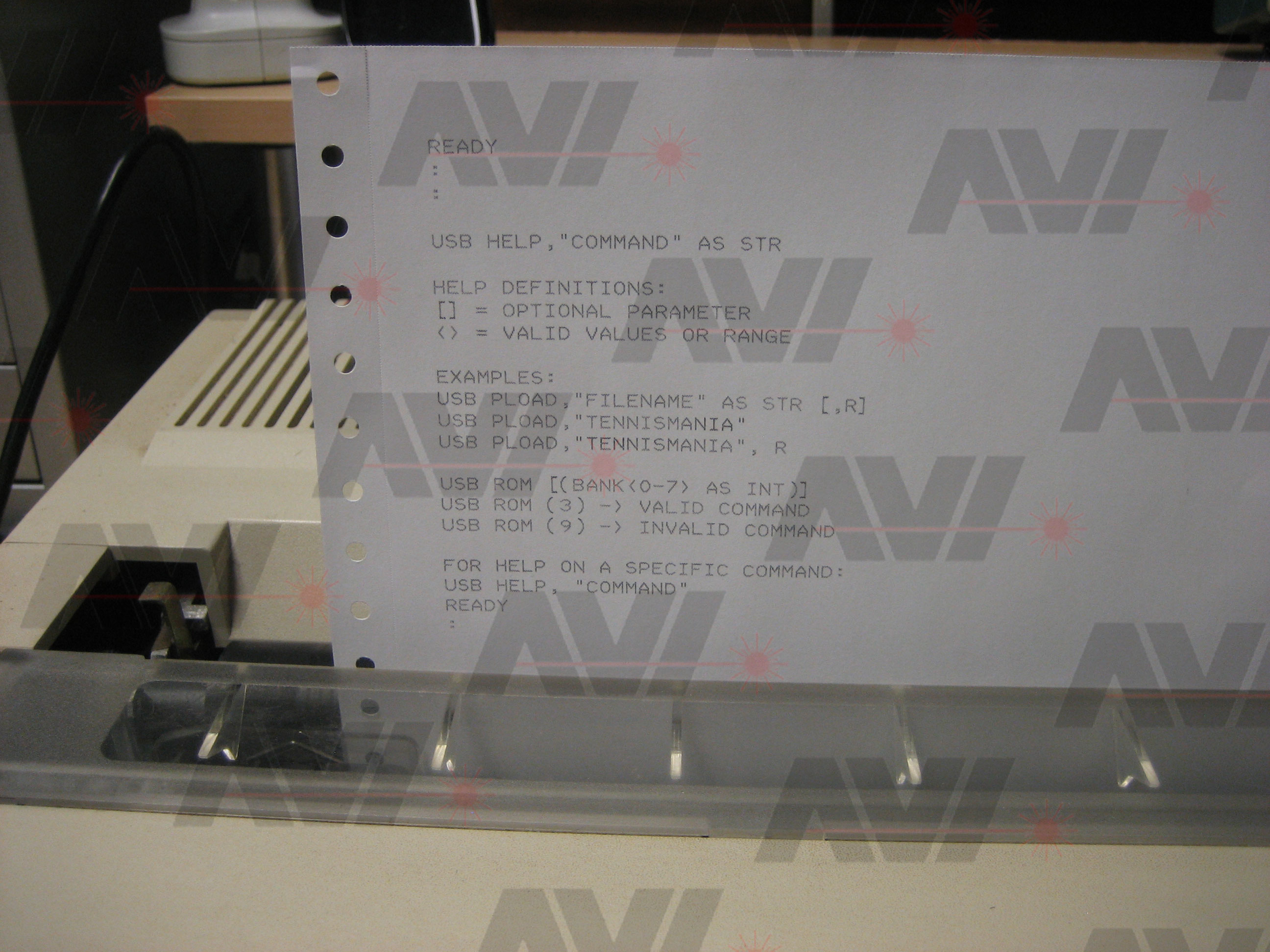
I played around with the other call addresses in the manual and was able to get a 'LIST' command to print out a Basic program that was loaded. Serial printing was working.
I only had to repair the parallel side, the serial portion worked fine.
RESEARCH
I still needed to know a few things about the jumpers on the card. Through tracing, testing and just trying them all I figured out what all the jumpers do.
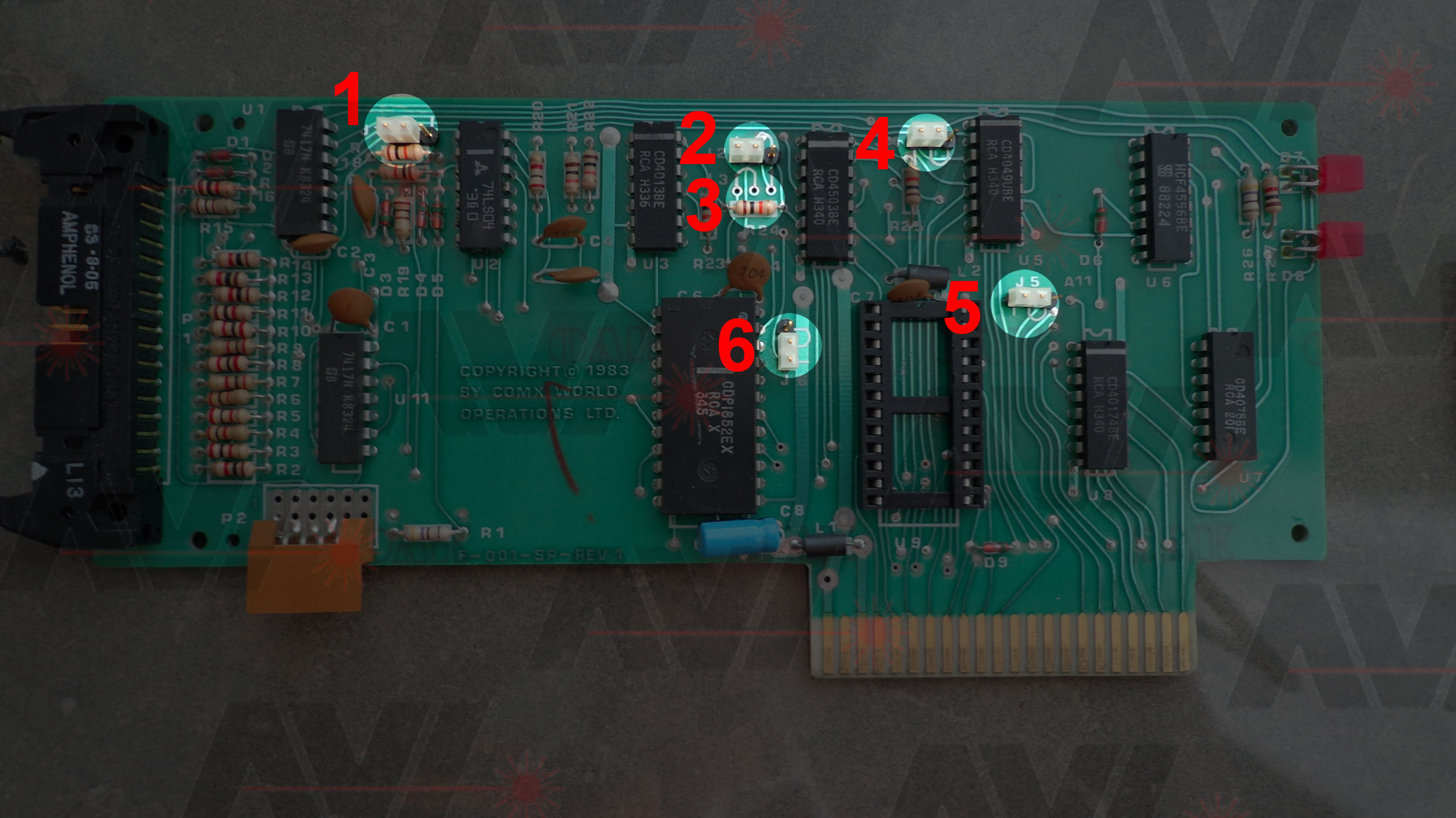
JUMPERS
- J1 Cable determines mode or Force Parallel
- J2 Paper Empty or /Paper Empty
- J3 Not used
- J4 Busy or /Busy
- J5 Serial ROM select or Parallel ROM select
- J6 Strobe or /Strobe
I was also able to work out the rest of the commands with help from Marcel.
PRINTER COMMANDS
PARALLEL
- CALL (@C050): Switch off the printer
- CALL (@C060): Switch on the printer with control character suppressed
- CALL (@C070): Switch on the printer
- CALL (@C080): Switch on the printer and TV display mode with control character suppressed
- CALL (@C090): Switch on the printer and TV display mode
- CALL (@C0A0): Disable keyboard input to printer
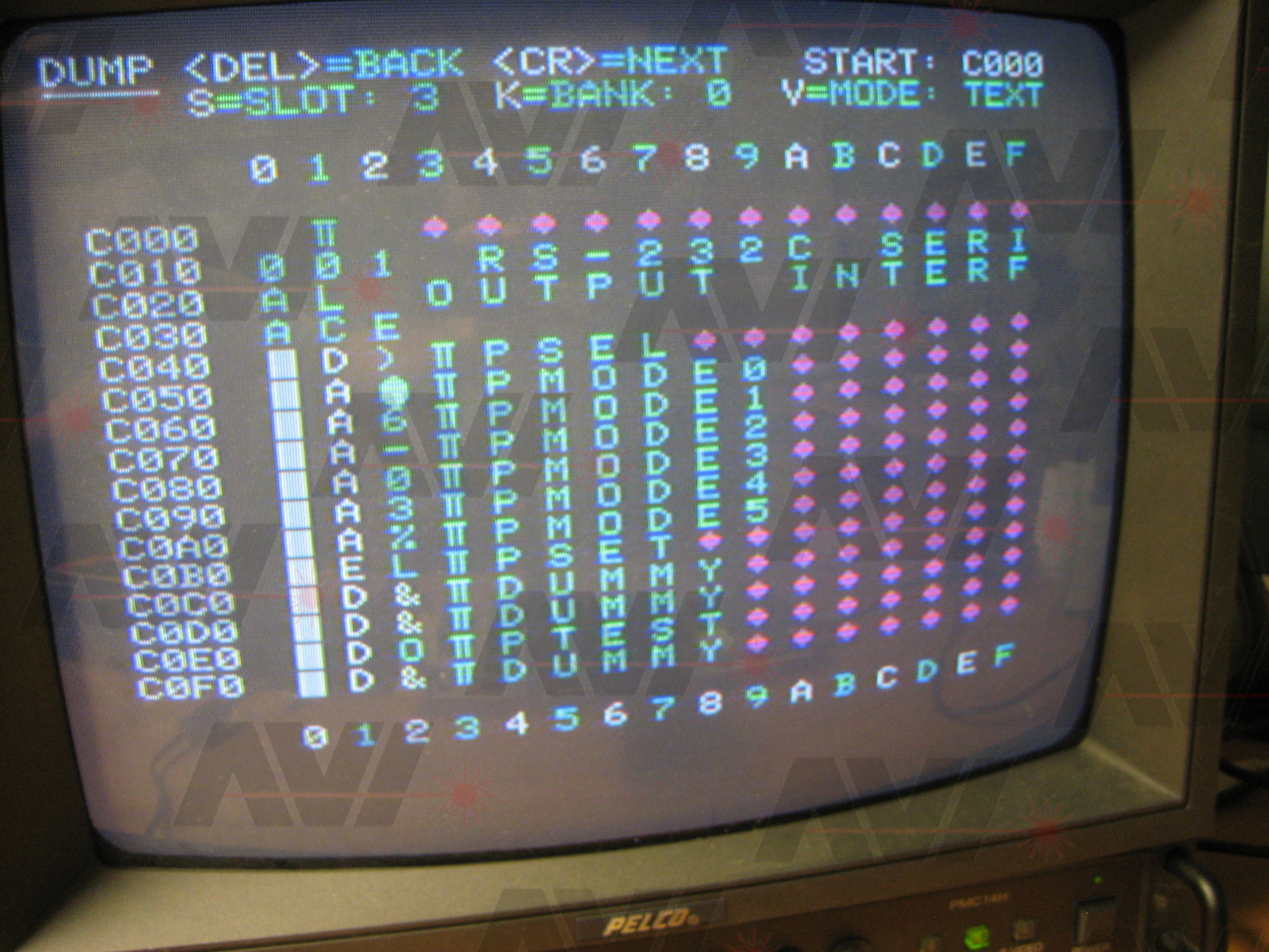
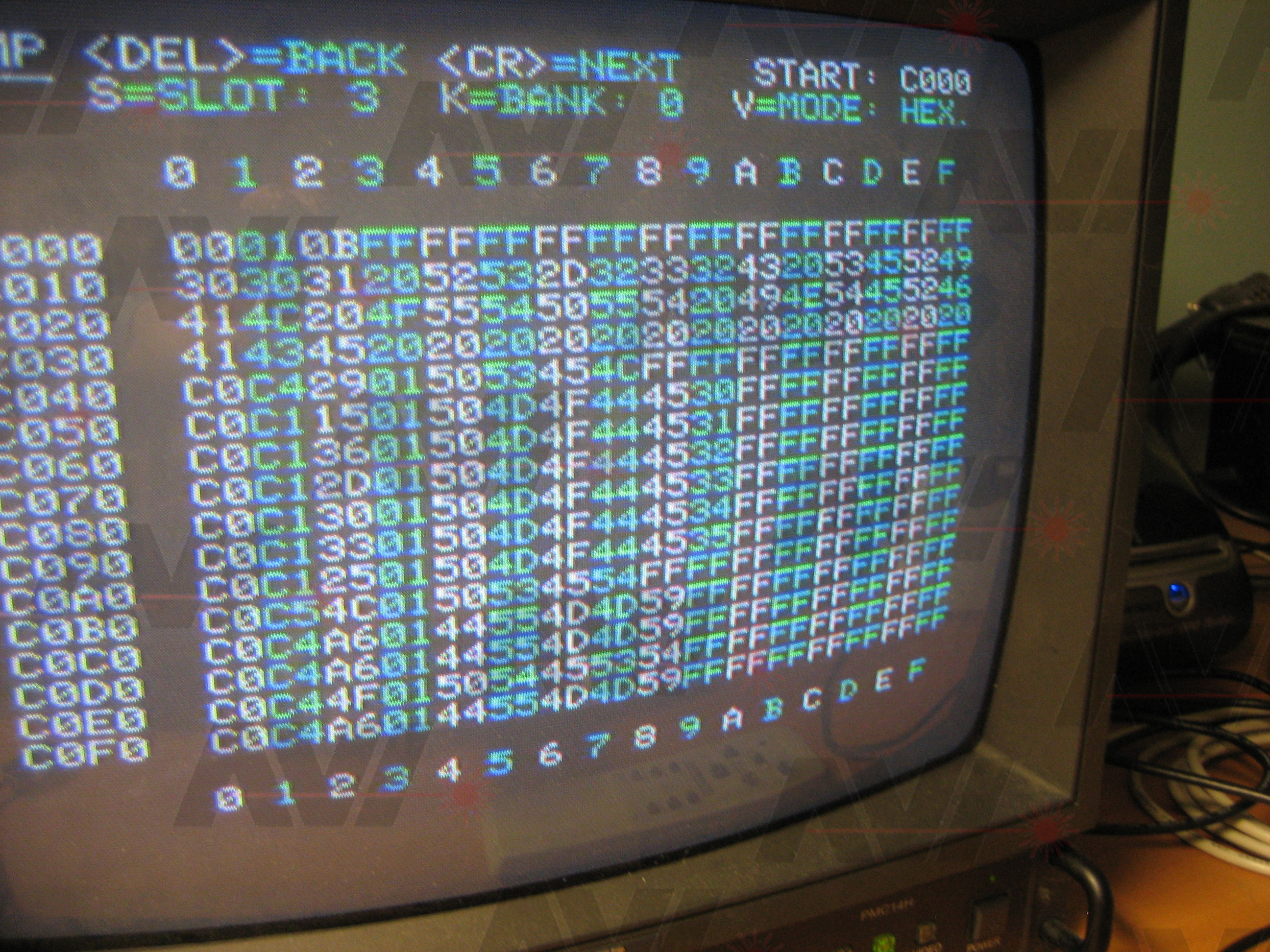
- CALL (@C0C0): Memory dump
- CALL (@C0E0): Self test
SERIAL
- CALL (@C050): Switch off the printer
- CALL (@C060): Switch on the printer with control character suppressed
- CALL (@C070): Switch on the printer
- CALL (@C080): Switch on the printer and TV display mode with control character suppressed
- CALL (@C090): Switch on the printer and TV display mode
- CALL (@C0A0): Disable keyboard input to printer
- CALL (@C0B0): Change RS232 Settings (you will be asked what settings)
BUILDING MY OWN PRINTER CARD
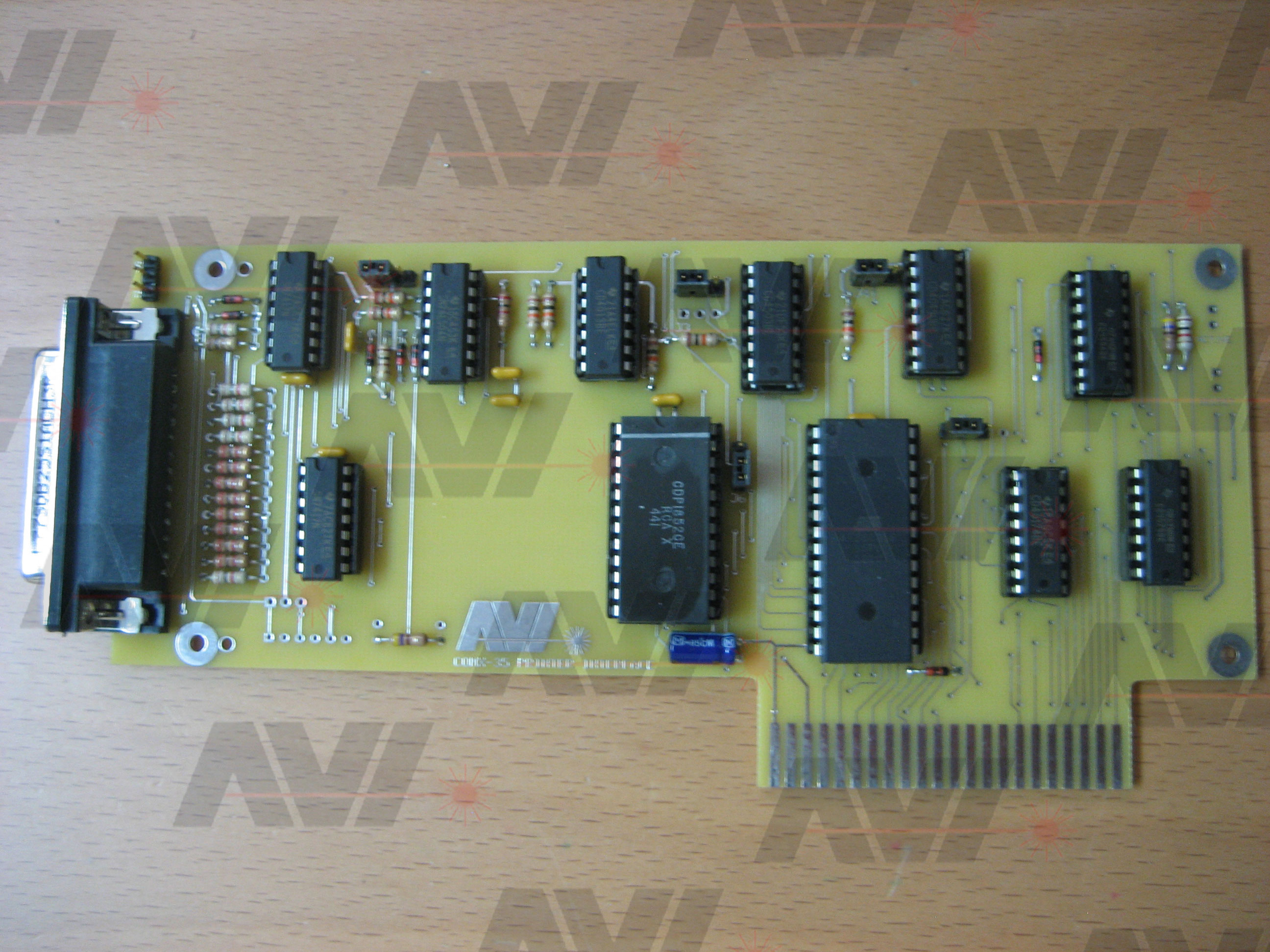
Using Marcel's board I was able to draw up a complete schematic of the printer board. From this I started designing a PCB.
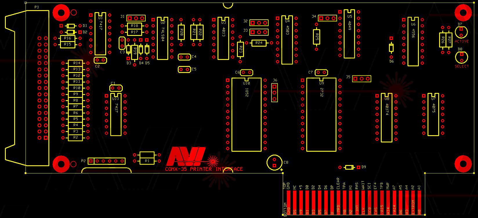
I tried to make it as close to the same layout as the original printer card. I made a couple of changes though. I used an AT28C256 EEPROM in place of the 2732 EPROM. I replaced the IDC-34 connector with a DB-25. This is fine for my board since it will never be put in a plastic case. The DB-25 is too tall to fit in a normal COMX expansion board case.
Here is what the PCB looks like:
And built up:
Here is a picture of the original printer card and the one I built:
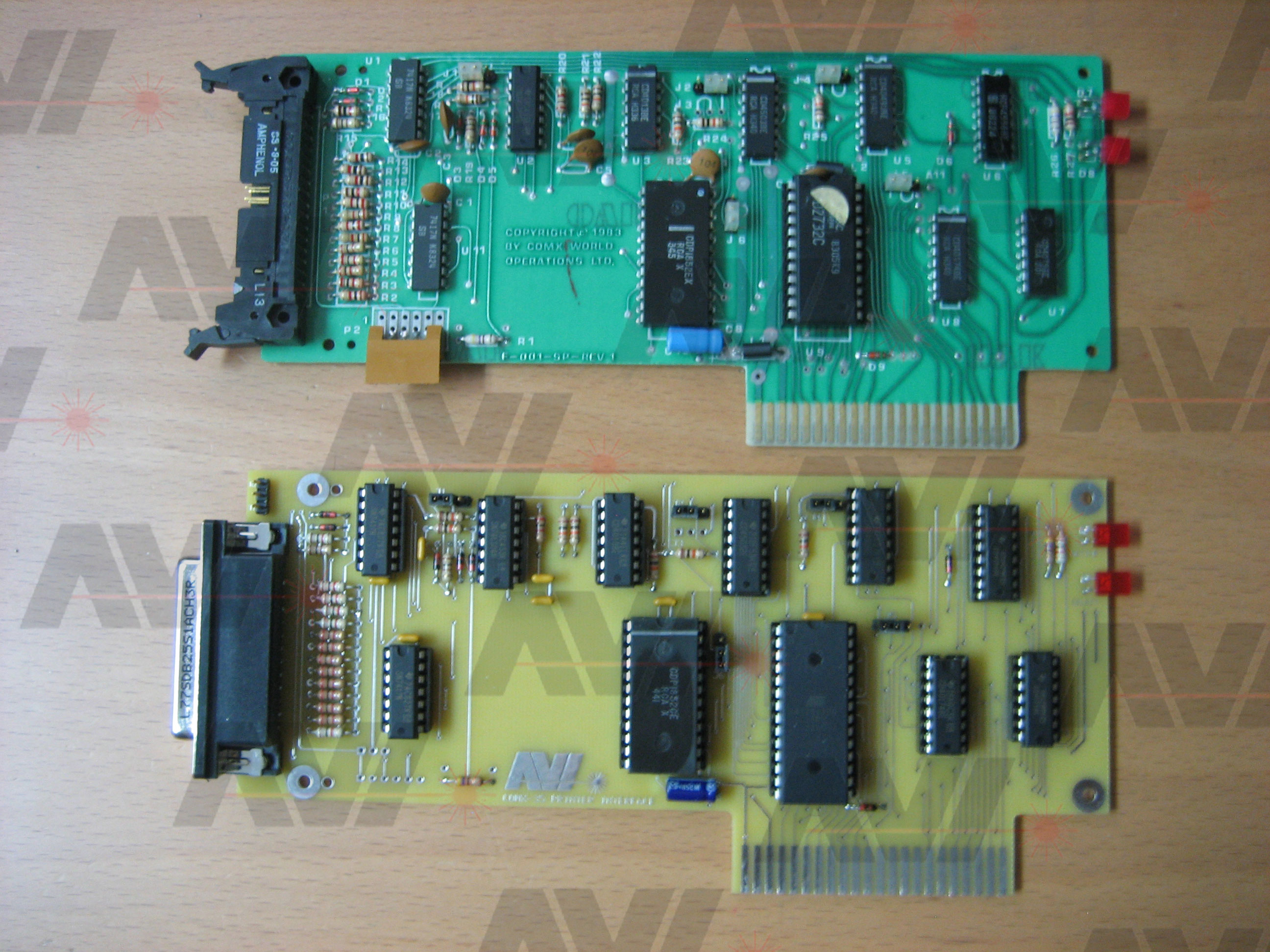
The original printer board uses a 6-pin, Molex style connector but only three pins are used. Right before I placed the order to have the PCBs made, I added two 3-pin connectors for serial connection options. One is right above the original 6-pin connector and the other is on the top of the board at the back edge above the DB-25.
In my haste I made a single, stupid, mistake that caused the serial section to not work. When I added one of the traces for the 3-pin connector, I accidentally placed it across one of the pads going to a resistor. I didn't catch this before ordering.
I needed to make 2 cuts and add 1 jumper. I have it fully working now, both parallel and serial.
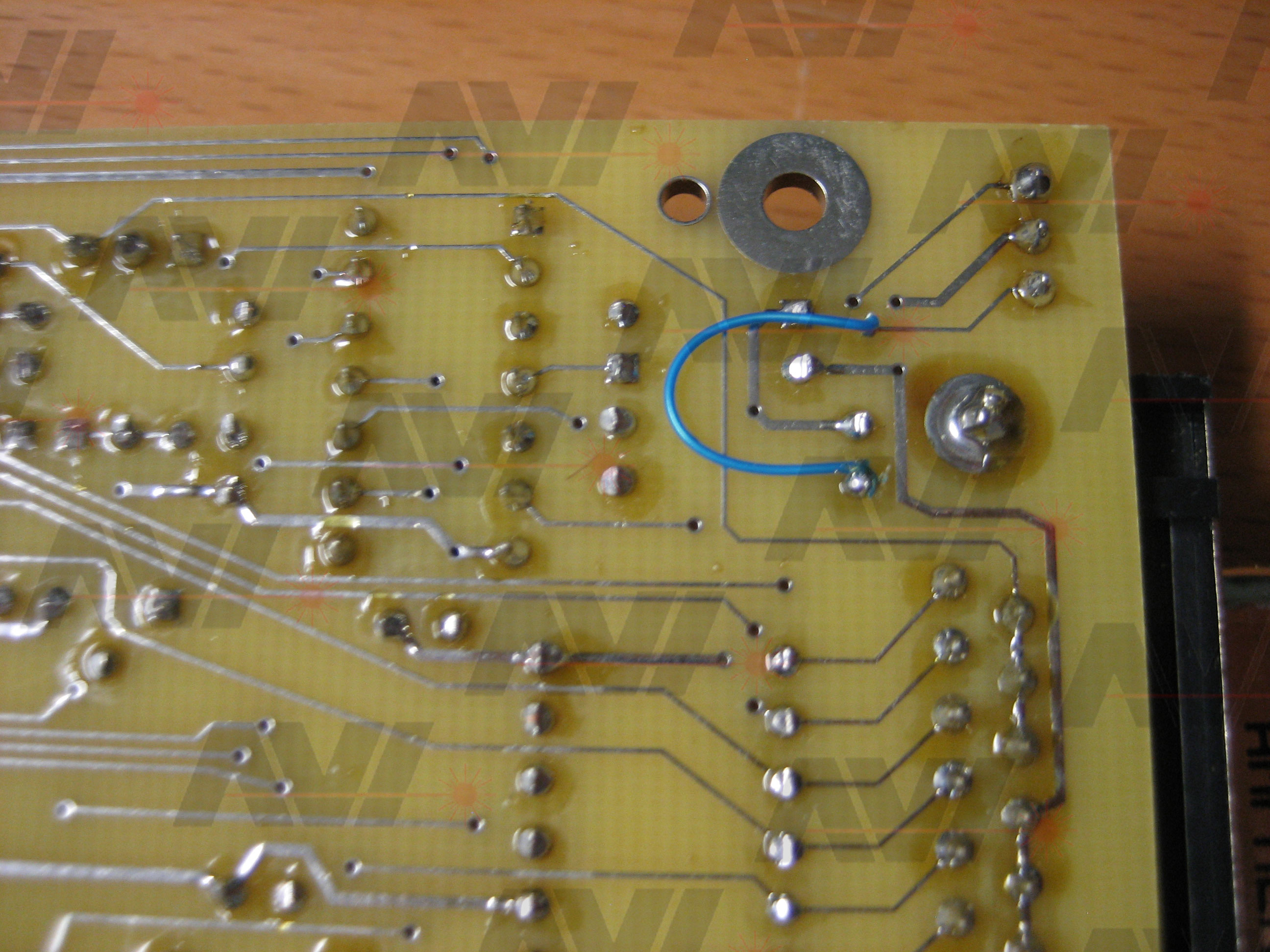
With that single repair, my COMX printer card is working fine.
Thank you for reading this. I hope you found it interesting.
ED